Printer Parts and Their Functions
Explanation of the parts on the printer and their functions.
Caution: To avoid printer damage, do not touch the code strip, the shaft, or the flat cable.Front View
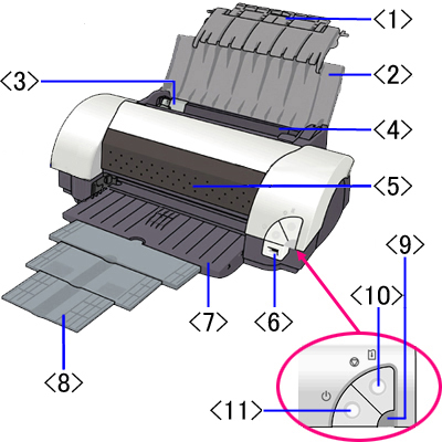
<1> Paper Rest Extension: Open the paper rest extension when printing on paper larger than A4.
<2> Paper Rest: Supports loaded paper. Open this before printing.
<3> Paper Guide: Pinch and slide to align to the left edge of the paper.
<4> Sheet Feeder: Load paper here. Multiple sheets of paper can be loaded (except for some particular types of paper). Feeds paper automatically sheet by sheet.
<5> Front Cover: Open to replace the ink tanks or to remove jammed paper.
<6> Direct Print Port: Connects the printer to a digital camera/video camera supporting Canon Bubble Jet Direct or PictBridge to perform Direct Printing.
<7> Paper Output Tray: Printed paper is ejected here. Turn this down before printing.
<8> Paper Output Tray Extension: According to the paper sizes to be printed, pull the paper output tray extension out as follows.
Note: When printing on paper smaller than B4, pull this out two steps. When printing on paper larger than B4, pull this out three steps. <9> Power Lamp: Indicates that the power is on/off and conditions of errors.
<10> Resume/Cancel Button: Press this to print again after an error is resolved, or to cancel printing in progress.
<11> Power Button: Press to turn the printer on or off.
Return to topRear View
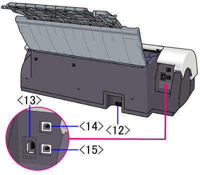
<12> Power Cord Connection: Connects the printer to a power source using the provided power cord.
<13> FireWire 400 port: Connects the printer to a computer via a IEEE1394 cable. This port has 6 pins.
Note: The IEEE1394 interface is for use only with Macintosh computers. The interface is not available for Windows.<14> USB 2.0 Hi-Speed Port (the upper port): Connects the printer to a computer via a USB cable.
<15> USB 2.0 Full Speed Port (the lower port): Connects the printer to a computer via a USB cable.
Return to topPrint Head / Carriage
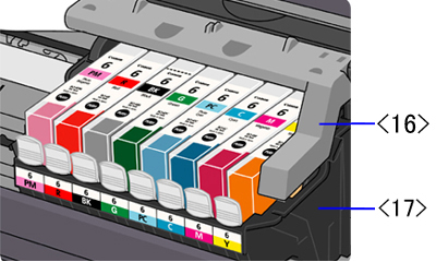
<16> Print Head Lock Lever: Locks the print head into the holder.
Note: Once the print head is installed, do not raise the print head lock lever, except to replace the print head.
<17> Print Head Holder: Holds the print head.
Return to topSerial Number
- The serial number of the printer is visible when the front cover is opened, as shown below.
- When confirming the serial number, ensure that the printer is powered off before opening the front cover.
- The serial number starts with 4 letters and ends with 5 digits.
- Example: VVPP00018

Return to top
Code Strip, Flat Cable and Shaft
Caution: To avoid printer damage, do not touch the code strip, the shaft, or the flat cable.

<1> Code Strip
<2> Shaft
<3> Flat Cable
Return to top
