Load Paper Correctly
To avoid paper jams, paper should be fanned and loaded into the Paper Tray correctly.
Adjusting the Paper Guide Printer Parts and Functions
Adjusting the Paper Guide
- Holding the paper guide tabs, move the paper guide to the left, and set the paper, aligning the paper with the right side of the sheet feeder.
- Move the paper guide until it lightly contacts the paper's left edge.
Note: If the paper guide heavily contacts the paper, paper feeding problems may occur. To move the paper guide, pinch and slide in the appropriate direction.
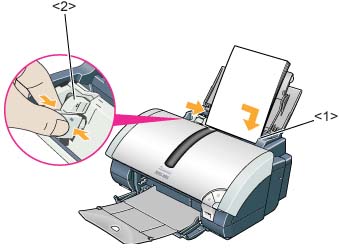
<1> Paper Guide
<2> Paper position
Printer Parts and Functions
Front View
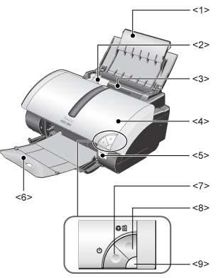
<1> Paper Rest: Supports loaded paper. Extend this before printing.
<2> Paper Guide: Pinch and slide to align to the left edge of the paper.
<3> Sheet Feeder: Load paper here. Multiple sheets of paper can be loaded (except for some particular types of paper).
<4> Front Cover: Open to replace the ink tanks or to remove jammed paper.
<5> Camera Port: Connects the printer to a digital camera/digital video camera supporting Canon Bubble Jet Direct or PictBridge to perform Direct Printing.
<6> Paper Output Tray: Printed paper is ejected here. Extend this fully before printing.
<7> Power Button: Press to turn the printer on or off.
<8> Resume/Cancel Button: Press this to print again after an error is resolved, or to cancel printing in progress.
<9> Power Lamp: Indicates that the power is on/off and conditions of errors.
Back View

<10> USB Port: Connects the printer to a computer via a USB cable.
<11> Printer Port: Connects the printer to computer via a standard printer cable (parallel cable).
<12> Power Cord Connection: Connects the printer to a power source using the provided power cord.
Inside view
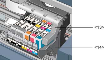
<13> Print Head Lock Lever: Locks the print head into the holder.
<14> Print Head Holder: Holds the print head.
Note:Once the print head is installed, do not raise the print head lock lever, except to replace the print head.
Return to the top.
