
Connecting the components to a VC-C50i / VC-C50iR
| Article ID: ART112757 | | | Date published: 05/11/2015 | | | Date last updated: 08/17/2015 |
Description
Solution
Connecting the components to a VC-C50i / VC-C50iR
Contents:
Connecting to the Multiconnector
Attaching the Multiconnector to the Camera

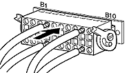
Connecting to the Multiconnector
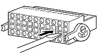
Use the procedure below to plug leads (AWG No.28-18) into the multiconnector plug.
|
1. Insert a flat-bladed screwdriver all the way into the slot next to the lead fastening hole. |
 |
| 2. With the screwdriver still inserted, push the end of the lead into the lead fastening hole. | 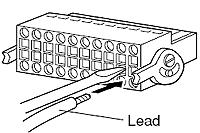 |
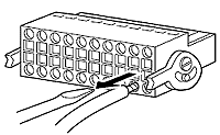
3. Holding the lead securely so that it does not come out of the lead fastening hole, pull out the screwdriver.
|
 |
Attaching the Multiconnector to the Camera
| 1. Raise the levers on each side of the multiconnector plug. | 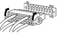 |
| 2. Push the multiconnector plug into the multiconnector socket. | 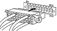 |
3. Push the multiconnector plug in fully.
|
 |
|
To remove the multiconnector, push the levers on sides downwards at the same time. |
|
Multiconnector Pin Layout
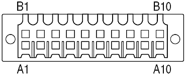
Key for the tables below:
| Abbreviation | Meaning |
| Y | S-Video luminance (brightness component of the video signal) |
| C | S-Video chrominance (color component of the video signal) |
| GND | Ground (signal return line) |
| OUT | Output (signal flowing from camera to another device) |
| IN | Input (signal flowing into the camera) |
| RTS | RS-232C (serial) Ready To Send |
| CTS | RS-232C (serial) Clear To Send |
| TX | Transmit Data |
| TXD | Transmit Data Daisychained (cascaded through device) |
| RX | Receive Data |
| RXD | Receive Data Daisychained (cascaded through device) |
| - | Negative |
| + | Positive |
|
Pin No. |
Pin Name |
Pin Name |
Pin No. |
|
A1 |
Y GND |
Y OUT |
B1 |
|
A2 |
C GND |
C OUT |
B2 |
|
A3 |
RTS OUT |
CTS OUT |
B3 |
|
A4 |
TX OUT |
RX OUT |
B4 |
|
A5 |
GND |
GND |
B5 |
|
A6 |
RTS IN |
CTS IN |
B6 |
|
A7 |
TX IN |
RX IN |
B7 |
|
A8 |
Light_ON/OFF- |
Light_ON/OFF+ |
B8 |
|
A9 |
Alarm_- |
Alarm_+ |
B9 |
|
A10 |
Sensor_- |
Sensor_+ |
B10 |
|
Item |
Pin No. |
Pin name |
Input/Output |
Signal direction |
Notes | |
|
S-video out |
A1 |
Y GND |
Output |
|
S-video luminance output GND | |
|
B1 |
Y OUT |
Output |
|
S-video luminance output | ||
|
A2 |
C GND |
Output |
|
S-video chroma output GND | ||
|
B2 |
C OUT |
Output |
|
S-video chroma output | ||
|
RS-232C |
A3 |
RTS |
Output |
|
RS-232C cascade output send request | |
|
B3 |
CTS |
Input |
NEXT CAMERA |
RS-232C cascade output send enabled | ||
|
A4 |
TXD |
Output |
|
RS-232C cascade output send data | ||
|
B4 |
RXD |
Input |
NEXT CAMERA |
RS-232C cascade output receive data | ||
|
A5 |
GND |
- |
- |
RS-232C cascade output GND | ||
|
RS-232C |
B5 |
GND |
- |
- |
RS-232C input GND | |
|
A6 |
RTS |
Output |
|
RS-232C input send request | ||
|
B6 |
CTS |
Input |
PC |
RS-232C input send enabled | ||
|
A7 |
TXD |
Output |
|
RS-232C input send data | ||
|
B7 |
RXD |
Input |
PC |
RS-232C input receive data | ||
|
External lighting control signal |
A8 |
Light_ON/OFF- |
Output |
Current input |
External lighting switch 50V/200mA (max.) | |
|
B8 |
Light_ON/OFF+ |
Output |
Current output |
External lighting switch 50V/200mA (max.) | ||
|
Alarm control signal |
A9 |
Alarm_- |
Output |
Current input |
Alarm control 50V/200mA (max.) | |
|
B9 |
Alarm_+ |
Output |
Current output |
Alarm control 50V/200mA (max.) | ||
|
External sensor input |
A10 |
Sensor_- |
Input |
Current input |
GND | |
|
B10 |
Sensor_+ |
Input |
Current output |
Pull-up to 5V, diode protected |
 MONITOR
External Device I/O Terminals
External device input terminals
These comprise 2 sensor terminals (positive (+) and negative (?)). The negative terminal is connected to the camera's own ground and the positive terminal is pulled up to 5 volts at 10 kohm via a protection diode. Connecting the respective leads to the positive and negative terminals and then shorting across the terminals (ON) or not (OFF) generates an interrupt for the controller. The power supplies and grounds for the connected sensors and switches should be connected to electrically segregated terminals. When an ON state is detected, an event occurrence is posted to the host PC.
External device output terminals
These comprise ON and OFF terminals for the alarm and light terminals, with equivalent terminals in directions for the respective combinations. The two terminals can be switched between conductive and resistive states using the controller. In addition, an optical connector is used in the output terminal and is separate from the circuits in the camera.
The load connected to the output terminal should be within the following ratings:
Rated values between output terminals:
Max. DC voltage: 50V
Continuous load current: 120 mA