
QuickGuide to Speedlite 600EX-RT Radio Wireless Flash Setup
| Article ID: ART170208 | | | Date published: 05/02/2018 | | | Date last updated: 06/23/2020 |
Description
QuickGuide to Speedlite 600EX-RT Radio Wireless Flash Setup
Solution
INTRODUCTION
The Speedlite 600EX-RT allows you to set up multiple Speedlites as “receivers” which are wirelessly controlled and synchronized by a “sender” unit. As compared to flash units that use optical signals only, the 600EX-RT’s radio-based wireless E-TTL offers significant advantages, such as the freedom to place 600EX-RT receiver units up to 98 feet from the camera and “sender unit”, all without a direct line-of-sight between the sender and receiver. Your wireless radio setup options include:
• Automatic E-TTL with equal output from all units
• Automatic Ratio E-TTL with unequal (ratio) output between firing groups
• M – Manually-set power output (you can set a different flash output for each receiver unit or firing group)
• GR – Different groups have different flash modes, with up to five groups
Only a 600EX-RT or ST-E3-RT Speedlite Transmitter attached to a camera can be a sender. You can, however, use two or more sender units by setting up multiple cameras, each with a sender unit attached, and switch from one to another during a wireless flash shooting session. The receiver lighting setup will remain the same. Only 600EX-RTs can be receiver when you are shooting in radio control mode.
COMPATIBILITY
EOS cameras released since 2012 (such as EOS-1D X, EOS 5D Mark III, EOS 6D, and EOS Rebel T4i) – full compatibility
EOS cameras released before 2012:
• Flash sync speed must be one stop slower than the maximum
• No high-speed sync shooting
• No group (GR mode) flash
Note: Full flash sync, including Hi-Speed Sync, is available with the 600EX-RT with all EOS SLRs when used in optical wireless E-TTL control mode.
INITIAL WIRELESS RADIO FLASH SETUP
You must first set the sender and receivers to matching transmission channels and wireless radio IDs. Once you have done so, any settings you make to the sender will automatically be transmitted to the receivers. This eliminates the need to adjust the receivers
individually and manually.
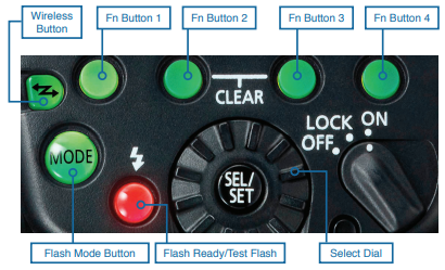
1. To set the sender unit: Press the Wireless Flash Button until the RT icon (upper-right corner of the unit’s LCD screen) and <MASTER> appear.
The wireless flash cycle via button is: Conventional on-camera flash > Radio-based Master unit > Radio-based Slave unit > Optical-based Master unit > Optical based Slave unit.
2. To set the receiver unit(s): Press the Wireless Flash Button until the RT icon and <SLAVE> appear.
3. To set the transmission channel: Set the sender and receiver units to the same Transmission Channel, otherwise the receiver(s) will not fire. Use the same procedure below for sender and receiver.
a. Press Fn Button 4 until <MENU 3> displays.
b. Press the channel button (Fn Button 1, under the “CH” icon). The channel number will highlight immediately below RT icon. Turn the selector dial to the channel number of your choice (1 to 15) or AUTO. If you set AUTO, the 600EX-RT will automatically set the channel with the best reception. Set the sender and receiver units to the same Wireless Radio Channel.
c. Press Fn Button 4 until <MENU 3> displays.
d. Press Fn Button 2 to highlight ID.
e. Turn the Select Dial to the digit you want to set. There are four digits.
f. Press the Select/Set Button to activate the digit setting.
g. Turn the Select Dial to set any digit from 0 to 9, then press the Select/Set Button to register your setting.
h. Repeat steps e – g to enter a four-digit number. You can enter any number from 0000 – 9999. The sender and receiver units must be set to same ID number. The number you set must be different from that of any other 600EX-RT shooter in the vicinity.
i. Press Fn Button 4 to return the flash to shoot-ready mode.
j. The <LINK> lamp should light green to indicate a working link between the sender and receiver, assuming both are turned on and set to same Channel/ID.
• If you are using more than one sender, the color of the <LINK> lamp will vary depending on the order in which you turn the senders on. The first/main sender is green. Subsequent/sub-senders are orange.
• If the LINK lamp is continuously red, check to make sure the sender and receiver are set to the same channel and ID.
• If the LINK lamp is blinking red, either your setup totals more than 16 units or you may need to turn the power off and on again.
SENDER FLASH FIRING ON/OFF
You can choose whether sender flash firing is ON and therefore the sender contributes to the flash exposure, or OFF and does not. The sender flash will still control the receivers, regardless of whether it contributes to the exposure.
1. Press Fn Button 4 until Menu 2 displays.
2. Press Fn Button 1 (under Flash On/Off icon) to ON or OFF
a. Three little beam lines coming from flash icon on LCD panel indicate Master Flash ON
b. Beam icons disappear when Master Flash OFF is active
WIRELESS E-TTL — “ALL” (FLASH RATIO OFF)
In this mode all flash units will fire at the same output, with full E-TTL auto flash exposure, which you can adjust with flash exposure compensation (FEC) on your camera, as necessary.
This mode is best for lighting setups where you want even lighting throughout the scene. E-TTL is also great when flash-to-subject distances may change from shot to shot.
1. Perform the initial flash setup described above. Confirm that sender and receiver are set to the same transmission channel and radio ID. Position the camera and flash within correct operating range (30 meters/98 feet.)
2. Set the firing group on each receiver unit. Set the receiver unit to firing group A, B, or C. The receiver will not fire if set to group D or E, when ratio control is set to ALL. You can assign multiple flash units to the same group.
3. Set the sender to radio-based Wireless E-TTL. Press the <MODE> button on the sender unit to set the sender to E-TTL.
4. Set the Ratio to “ALL” — On sender unit, press Fn Button 4 (under “Menu 1” icon) until Menu 2 appears. Press Fn Button 2 (under “Ratio” icon) until “ALL” appears on sender unit’s LCD panel.
5. Confirm wireless link. Confirm that the <LINK> lights on the 600EX-RT’s are lit and green and that the AF-assist beam emitter on the receiver is blinking at 1-second intervals. Also confirm that the red flash ready light is lit on the sender unit.
6. Shoot.
a. Press the test flash button on the sender flash to check operation. If a receiver does not fire, make sure it is within the correct range.
b. Take the picture. The flash exposure confirmation lamp will light for 3 secs to confirm normal exposure.
c. The sender flash’s flash-ready light will illuminate when all flash units have recycled. You can enable C.Fn-20 on the sender unit to also trigger an audible beep when the receivers have recycled.
WIRELESS E-TTL WITH RATIO CONTROL
In this mode you can divide the receiver units into different firing groups (A:B or A:B C) and control the flash ratio (relative output) between them. You can then adjust the overall brightness with flash exposure compensation (FEC) on your camera, as necessary.
This mode is best for lighting setups where the flash-to-subject distance may change from one shot to the next and you wish to maintain consistent output ratios between flash units.
1. Perform the initial flash setup described above. Confirm that sender and receiver are set to the same transmission channel and radio ID. Position the camera and flash within correct operating range (30 meters/98 feet).
2. Set the firing group on each Speedlite 600EX-RT receiver unit:
a. With Menu 1 displayed on a receiver unit’s LCD panel, press Fn. Button 3 on the sender unit (under the “GR” icon).
b. Set one unit to <A> and at least one receiver unit to <B> (do not set a receiver unit to “D” or “E”, since it won’t fire in those settings).
3. Set the ratio on the sender unit:
a. Press the sender unit’s Fn Button 4 to display <Menu 2>.
b. Press Fn Button 2 (under the “Ratio” icon), to toggle between <ALL>, <A:B> or <A:B C>.
Note: A:B requires a minimum of two units. A:B C requires a minimum of three. In either case, you can adjust the power ratio only between groups A and B. Group C is independent of A and B, and is best used for background or accent lighting, rather than lighting the main subject.
c. Press Fn Button 3 under the “GR” icon.
d. Press Fn Button 3 again to display <A:B ±>, and highlight the ratio scale.
e. Turn the Select Dial to set the flash ratio, then press the Select/Set Button.
f. Press Fn Button 4 to return to shoot-ready mode.
All flash ratios are expressed as A relative to B and as relative amounts of exposure. For example, “1:1” means firing groups A and B will produce equal output, “2:1” means A will produce twice as much output (one stop more) than B, “1:2” means B will
produce twice as much output as A, and “8:1” means A will produce eight times (3 stops) more output than B.
E-TTL GENERAL NOTES
1. Flash coverage is set to 24mm by default when the Speedlite 600EX-RT is set for wireless operation. You can manually set the flash head to a more narrow angle of coverage if you wish.
2. Press the depth-of-field preview button on the camera if you want to fire the modeling flash.
3. If you’ve set Master Flash ON, the sender unit is always part of the A Group—no exceptions.
4. When set for radio-based wireless flash, the sender flash unit will enter sleep mode (auto power-off) after 5 minutes of inactivity. Activative Speedlite 600EX-RT Custom Function 01-1 if you wish to disable sleep mode on the sender unit.
5. If a receiver enters sleep mode, press the sender unit’s test flash button to turn the receiver back on. Receiver units, by default, stay active for 60 minutes before auto power-off. You can use Flash C.Fn 10-1 to change this to 10 minutes to conserve receiver unit battery power.
6. The following flash settings are available during radio-based Wireless E-TTL (set on the sender unit):
• Flash exposure compensation
• Flash exposure bracketing
• Flash exposure lock
• High-speed sync
• Manual flash
• Stroboscopic flash