Names of Parts (EOS C500 Mark II)
| Article ID: ART176197 |
| |
Date published: 01/28/2020 |
| |
Date last updated: 01/28/2020 |
Description
Below are diagrams and descriptions of th eparts of the camera.
Solution
Names of Parts
Camera
|
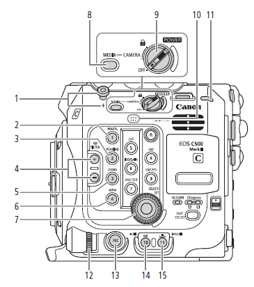 |
- Tape measure hook and
 focal plane mark focal plane mark
- MAGN. (magnification) button /
Assignable button Camera 1
- PEAKING button /
Assignable button Camera 2
- ND FILTER +/- buttons
- ZEBRA button /
Assignable button Camera 3
- WFM (video scope) button /
Assignable button Camera 4
- SELECT dial/SET button
- MEDIA button
When the camera is on, press to toggle the
camera between CAMERA mode (shooting) and
MEDIA mode (playback).
|
 switch switch
Set CAMERA to turn on the camera or to OFF
to turn it off.- Built-in monaural microphone
- Power indicator/Rear tally lamp
- Control dial
- REC (start/stop recording) button
- WB (white balance) button /
Assignable button Camera 10
 (play/pause) button (play/pause) button
 (white balance adjustment) button / (white balance adjustment) button /
Assignable button Camera 11 /
INDEX button
 (stop) button (stop) button
|
Locking the camera's controls (key lock)
You can set the  switch to switch to  (key lock) to lock all the camera's buttons and switches. This is useful in preventing settings from being changed due to inadvertently pressing one of the buttons. Set the switch back to CAMERA to reactivate the controls. (key lock) to lock all the camera's buttons and switches. This is useful in preventing settings from being changed due to inadvertently pressing one of the buttons. Set the switch back to CAMERA to reactivate the controls.
When the camera's controls are locked, you can still operate the camera using an optional RC-V100 Remote Controller or the Browser Remote application.
* In CAMERA mode, REC buttons are not locked by default but you can choose to lock them too. |
| |
 |
 (illumination) button (illumination) button
Turns on/off the illumination of the buttons on the
camera's left and back sides. This is convenient
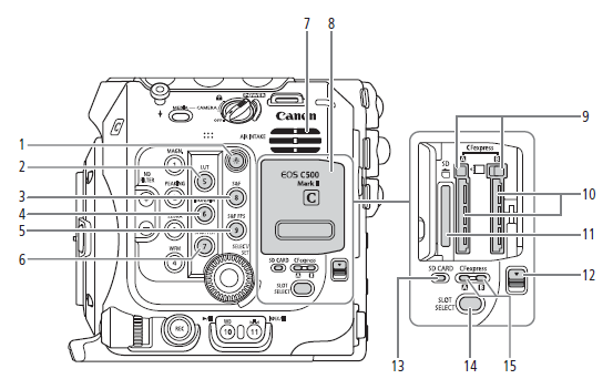
for night time or black-out operation.- LUT button /
Assignable button Camera 5
- S&F (slow & fast motion recording) button /
Assignable button Camera 8
- ISO/GAIN button /
Assignable button Camera 6
- S&F FPS (slow & fast shooting frame rate) button /
Assingable button Camera 9
- SHUTTER (shutter speed mode) button /
Assignable button Camera 7
|
- Air intake vent
- Card compartment cover
- CFexpress card release buttons: for CFexpress

(left), CFexpress  (right) (right)
- CFexpress card slots: for CFexpress (left),
CFexpress (right)
- SD card slot
- Card compartment cover switch
- SD CARD access indicator
- SLOT SELECT (CFexpres card selection) button
- CFexpress card access indicators: for CFexpress
(left), CFexpress (right)
|
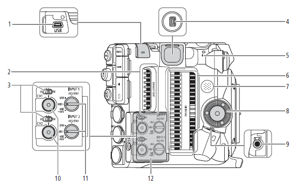 |
- USB terminal
For connecting the optional GP-E2 GPS Receiver.
- Exhaust ventilation outlet
- Audio level switches for CH1 (top) and CH2
(bottom)
- System expansion terminal
- Focal plane mark
- Air intake vent
- Speaker
|
- Camera grip attachment thread/Rosette
Compliant with ARRI rosettes.
- GRIP (camera grip connection) terminal
- Audio level dials for CH1 (top) and CH2 (bottom)
- INPUT 1 (top) / INPUT 2 (bottom) switches
(audio source selection)
- Cover for audio controls
|
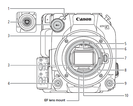 |
- Front tally lamp
- VIDEO terminal
- Lens mount fixation bolts
- PUSH AUTO IRIS (momentary automatic aperture)
button /
Assignable button Camera 14
- EF-S lens mount index
|
- EF lens mount index
- Lens release button
- EF lens lock pin
- ONE-SHOT AF (focus automatically once) button /
Assignable button Camera 15
- EF lens contacts
|
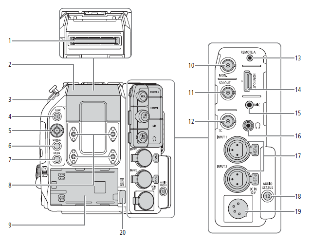 |
- Expansion unit connector
For connecting the optional EVF-V50 OLED
Electronic Viewfinder, EU-V1 Expansion Unit or
EU-V2 Expansion Unit 2.
- Expansion unit connector cover.
- Power indicator/Rear tally lamp
- FUNC (main functions) button /
Asignable button Camera 12
- Joystick
- CANCEL button
- MENU button
- Screw holes for M4 bolts (7.5 mm (0.30 in.) deep,
x4)
- Battery compartment
- MON. terminal
- SDI OUT terminal
|
- TIME CODE terminal
- REMOTE A terminal
For connecting the optional RC-V100 Remote
Controller or commercially available remote
contorllers.
- HDMI OUT terminal
- MIC (microphone) terminal
 (headphone) terminal (headphone) terminal- INPUT terminals (XLR): INPUT 1 (top), INPUT 2
(bottom)
- AUDIO STATUS (display the [
 Audio Setup] Audio Setup]
status screens) button /
Assignable button Camera 13
- DC IN 12V terminal
- BATTERY RELEASE button
|
Removing and attaching the terminal covers
You can remove the covers of the camera's terminals to access them more easily. To remove the terminal's cover, open the cover and gently pull it straight out. To attach back the terminal cover, insert the connecting strip into the opening.
 NOTES NOTES
- If the connecting strip is difficult to grasp, use a pair of tweezers or similar tool.
|
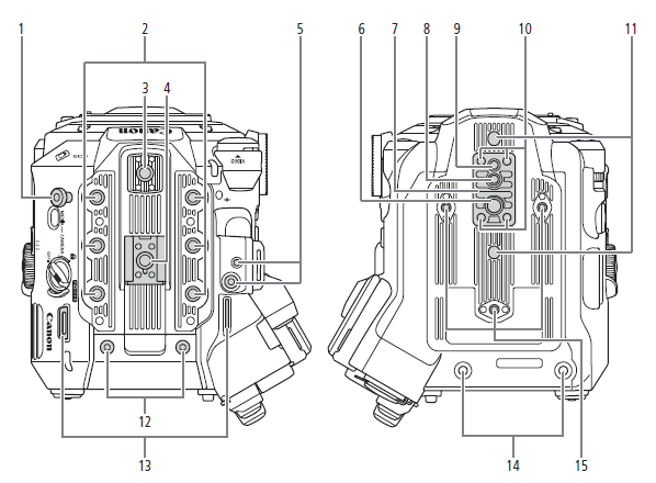 |
- Tape measure hook
Use the hook to accurately measure the distance
from the focal plane.
- Screw holes for 1/4"-20 mounting screws
(9 mm (0.35 in.) deep, x6)
- Top accessory mount with socket for 1/4"-20
mounting screws.
(6.7 mm (0.26 in.) deep)
- Accessory shoe with socket for 1/4"-20 mounting
screws (6.7 mm (0.26 in.) deep)/
Handle attachment unit
- Socket for the expansion system attachment
bracket
- Screw hole for 3/8"-16 mounting screws
(10 mm (0.39 in.) deep)
- TB-1 Tripod Base
- Socket for tripod's anti-rotation pin
(5.5 mm (0.22 in.) deep)
For tripods with 3/8"-16 mounting screws.
- Screw hole for tripods with 1/4"-20 mounting
screws (7 mm (0.28 in.) deep)
- Tripod base screws
|
- Sockets for tripod's anti-rotation pin
(5 mm (0.20 in.) deep, x2)
For tripods with 1/4"-20 monting screws.
- M4 screws for expansion unit connector cover
- Strap mounts
Pass the ends of the supplied shoulder strap
through the strap mounts and adjust the length of
the strap

- Expansion unit fixation screw holes (M4, x2)
- Screw holes for tripod reinforcements and
accessories with 1/4"-20 mounting screws
(7.5 mm (0.30 in.) deep, x3)
|
 IMPORTANT IMPORTANT
- Do not use tripods and other accessories with mounting screws exceeding the depth of the screw holes on the camera as this may damage the camera.
- Mounting the camera on a tripod using only one of the 1/4"-20 screw holes for tripod reinforcement may damage the camera.
|
| |
LM-V2 LCD Monitor
|
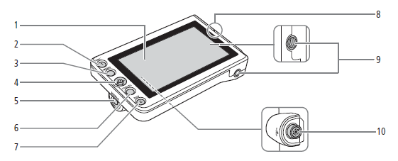 |
- LCD panel with touch screen
- FUNC (main functions) button /
Assignable button LCD LM-V1/V2 1
- MENU button
- Joystick
- MIRROR (invert the displayed image) button
- CANCEL button
|
- DISP (display) button /
Assignable button LCD LM-V1/V2 2
- LCD monitor's position alignment mark

- Screw holes for 1/4"-20 screws
(11.2 mm (0.44 in.) deep, x2)
- VIDEO terminal
|
| |
LA-V2 LCD Attachment Unit
|
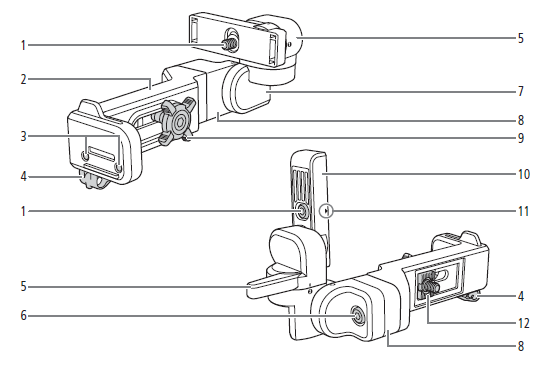 |
- LCD monitor fixation bolt
- Base 1
- Sockets for the microphone holder
- Cable clamp
- Pivot A
- Base 2 fixation bolt
|
- Pivot B
- Base 2
- Locking knob
- LCD monitor mount
- LCD monitor's position alignment mark
- Attachment mount
|
| |
Microphone Holder
|
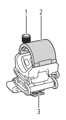 |
- Microphone lock screw
- Microphone holder
- Microphone cable clamp
|
|
| |
GR-V1 Camera Grip
|
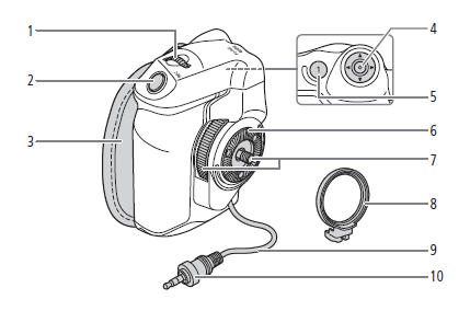 |
- Control dial
- REC (start/stop recording) button
- Grip belt
Adjust the grip belt so that you can reach the REC
button on the camera grip with your index finger
but still have a comfortable but secure grip.
|
- Joystick
- FOCUS GUIDE button /
Assignable button Camera Grip 1
- Rosette
Compliant with ARRI rosettes.
- Locking screw
- Grip attachment ring
- Grip connection cable
- Connection plug
|
| |
Handle Unit
|
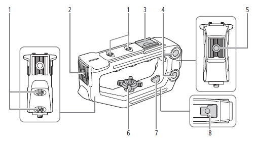 |
- Screw holes for 1/4"-20 screws
(6 mm (0.24 in.) deep, x4)
- Front accessory mount with socket for 1/4"-20
screws (8.8 mm (0.35 in.) deep)
- Top accessory shoe
- Through-holes (
 8.8 mm (0.35 in.), distance 8.8 mm (0.35 in.), distance
center-to-center 35.5 mm (1.4 in.))
|
- Rear accessory mount with socket for 1/4"-20
screws (8.8 mm (0.35 in.) deep)
- Locking knob
- Rear mounting hole (through-hole)
- Mounting base
|
| |
