|
|
Displaying Onscreen Markers, Zebra Patterns and False Color with EOS C700 models
| Article ID: ART174760 |
| |
Date published: 06/18/2019 |
| |
Date last updated: 06/18/2019 |
Description
Using onscreen markers allows you to make sure your subject is correctly framed and is within the appropriate safe area. The zebra patterns help you identify areas that are overexposed. The false color display allows you to check if the exposure is correct. You can choose to activate these assistance displays independently on the optional viewfinder or on external monitors. The assistance displays will not affect your recordings.
Solution
Displaying Onscreen Markers
The camera offers 6 types of onscreen markers. You can display multiple onscreen markers simultaneously.
- Open the [Markers] submenu.
MENU/EVF  [Assist. Functions] ( [Assist. Functions] ( ) )  [Markers] [Markers]
- Select [VIDEO Output] and/or [MON.+HDMI Output], select [On] and then press SET.
- Alternatively, you can press an assignable button set to [Markers: VIDEO] (optional viewfinder only), [Markers: MON.+HDMI] (external monitors only) or [Markers] (all monitoring devices at once).
- Onscreen markers are activated on all video outputs by default. Select [Off] instead to not display the onscreen markers on the respective video outputs.
- Select a marker you wish to display, select the desired marker color and then press SET.
- Select [Off] to turn off the selected marker.
- You can display multiple markers simultaneously. Repeat this step as necessary.
- If you selected [Safe Area] or [Aspect Marker], select the desired safe area or aspect ratio with the following procedures.
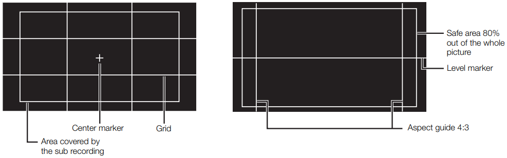
Options
| [Center]: |
Displays a small marker that indicates the center of the frame. |
| [Horizontal]: |
Displays a horizontal line to help you compose level shots. |
| [Grid]: |
Displays a grid that allows you to frame your shots correctly (horizontally and vertically). |
| [Aspect Marker]: |
Displays markers that indicate various aspect ratios to help you keep your shot within that area.
Available options for [Aspect Ratio] are [4:3], [13:9], [14:9], [16:9], [1.375:1], [1.66:1], [1.75:1], [1.85:1], [1.90:1], [2.35:1], [2.39:1], and [Custom], a free aspect ratio set by the user. |
| [Safe Area]: |
Displays indicators that show various safe areas, such as the action safe area and text safe area.
You can select the core area used as the basis for calculating the safe area and a percentage ([80%], [90%], [92.5%] or [95%]), relative to that core area. |
| [Sub Rec Area]: |
Displays a marker that indicates the area covered by the sub recording. |
 |
To set the aspect ratio
- Select [Aspect Ratio], select the desired option and then press SET.
- If you selected one of the preset aspect ratios, the rest of the procedure is not necessary. If you selected [Custom], continue the procedure to set the desired aspect ratio.
- Select [Custom Ratio] and then press SET.
- Set the desired aspect ratio using the keyboard screen.
To set the safe area
If an aspect marker is not selected, the safe area will be calculated as a percentage of the whole image ([Whole Picture]) and you can only select the percentage (step 2). To calculate the safe area as a percentage of an aspect ratio marker ([Selected Aspect Marker]), select an aspect ratio marker in advance and perform the procedure from the beginning.
- Select [Basis for Safe Area], select the desired option and then press SET.
- Select [Safe Area %], select the desired percentage and then press SET.
 NOTES
- The aspect ratio marker will not be displayed when the marker's ratio (including custom ratios) matches that of the resolution set in the video configuration.
Displaying Zebra Patterns
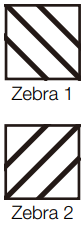
| The camera has a zebra pattern function that shows black and white diagonal stripes over areas that are overexposed. There are two types of zebra patterns and you can display both simultaneously. Zebra 1 lets you identify areas within a certain range (±5% of a specified level from 5% to 95%) while zebra 2 lets you identify areas that are over a specified level (from 0% to 100%). When you display both simultaneously and they overlap, only the zebra 1 pattern will be displayed in those areas. |
 |
- Open the [Zebra] submenu.
MENU/EVF [Assist. Functions] () [Zebra]
- Select [VIDEO Output] and/or [MON.+HDMI Output], select [On] and then press SET.
- Alternatively, you can press an assignable button set to [Markers: VIDEO] (optional viewfinder only), [Markers: MON.+HDMI] (external monitors only) or [Markers] (all monitoring devices at once).
- Select [Off] instead to not display the onscreen markers on the respective video outputs.
- From the same submenu select [Select] to set the zebra pattern type.
- Select [Zebra 1], [Zebra 2] or [Zebra 1+2] and then press SET.
- From the same submenu select [Zebra 1 Level] or [Zebra 2 Level] to set the trigger level.
- Select the desired value/range and then press SET.
NOTES
- When the HDMI OUT terminal's resolution is set to 4096x2160 or 3840x2160, zebra patterns will not be displayed on the monitor connected to the HDMI OUT terminal.
Using the False Color Display
The false color display is an assistance display mode that turns the image from the camera to black and white and overlays on it 6 different colors to indicate important brightness ranges.
Press the FALSE COLOR button on the camera to turn on the fasle color display on external monitors connected to the MON. terminals or the HDMI OUT terminal. Press the FALSE COLOR button on the optional viewfinder too turn on the flase color display on the viewfinder.
- You can also set MENU/EVF [Assist. Functions] [False Color] [VIDEO Output], [MON.1 Output], [MON.2 Output] or [HDMI Output] to [On] to activate the false color display on the respective monitoring devices.
- Alternatively, you can press an assignable button set to [False Color: VIDEO] (optional viewfinder only), [False Color: MON.+HDMI] (external monitors only), [False Color: MON.1], [False Color: MON.2], [False Color: HDMI] (individual monitors) or [False Color] (all monitoring devices at once).
NOTES
- You can use the MENU [Assist. Functions] [False Color] [Color Index] setting to display an index of the colors used in the false color display on the control display.
| Color |
Meaning |
| Red |
White clipping |
| Yellow |
Just below white clipping |
| Pink |
One stop over 18% gray |
| Green |
18% gray |
| Blue |
Just above black clipping |
| Purple |
Black clipping |
- The false color display will not be output in the following cases.
- When the HDMI OUT terminal's resolution is set to 4096x2160 or 3840x2160, the false color display will not be displayed on the monitor connected to the HDMI OUT terminal.
- While color bars are being displayed.
|
