|
Introduction
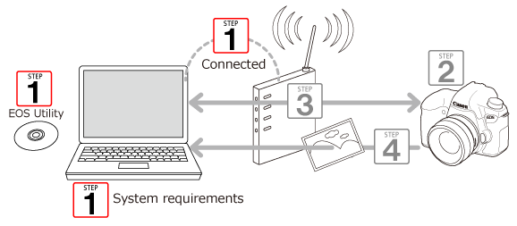
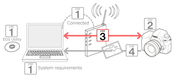
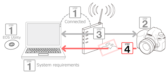
The following 4 steps explain how to send images from the camera to a computer via Wi-Fi. Start the operation from step 1.
 Step 1. Prepare necessary items.  Step 2. Configure basic settings for the camera.  Step 3. Connect the camera and the computer.  Step 4. Send images to the computer.
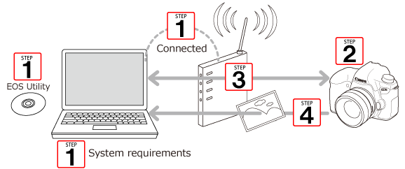
Step 1. Prepare Necessary Items
1. Check the environment on your computer.
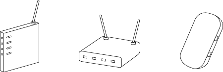
2. Make sure that a base station (like a wireless router) to be used as an access point is connected to the computer.
NOTE
- A router is a device used when establishing a network (LAN) by connecting multiple computers and other devices. A router with built-in Wi-Fi functions is called a "wireless router".
- For convenience in this article, wireless routers and other Wi-Fi base stations are referred to as "access points".
- If you are not sure of your computer environments, refer to the user manual supplied with your computer.
3. Make sure that the included software "EOS Utility" is installed on the computer.
IMPORTANT
- Settings may be disabled when an older version of software is used. Use a version of software installed from the CD supplied with this camera.
Step 2. Configure Basic Settings For the Camera
Configure necessary settings before using the wireless LAN functions of the camera.
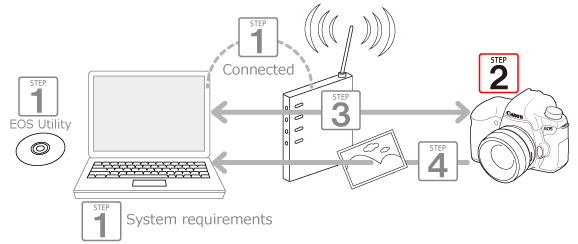
1. Turn on the camera.
- Set the camera's power switch to <ON>.
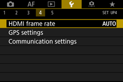
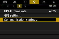
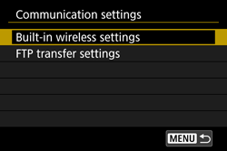
2. Under the [  ] tab, select [Communication settings].
- Press the <MENU> button to display the menu.
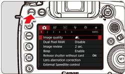
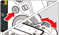
- Press the <
 > button, then turn the < > button, then turn the <  > dial to select the [ ] tab. > dial to select the [ ] tab.
- Turn the <
 > dial to select [Communication settings], then press < > dial to select [Communication settings], then press <  >. >.
3. Select [Built-in wireless settings].
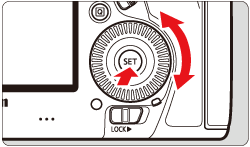
- Turn the < > dial to select [Built-in wireless settings], then press < >.
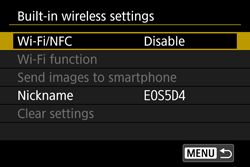
4. Select [Wi-Fi/NFC].
- Turn the < > dial to select [Wi-Fi/NFC], then press < >.
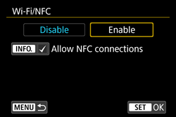
5. Select [Enable].
- Turn the < > dial to select [Enable], then press < >.
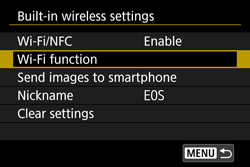
[Wi-Fi function] is now selectable.
REFERENCE
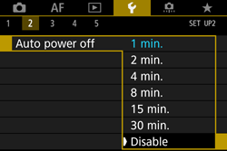
Under the [  ] tab, set [Auto power off] to [Disable] as necessary.
- If the Auto power off function of the camera takes effect while a connection is made via wireless LAN, the wireless LAN is disabled temporarily. The wireless LAN starts working again when the camera wakes up from the power off state.
6. Select [Wi-Fi function].
- Turn the < > dial to select [Wi-Fi function], then press < >.
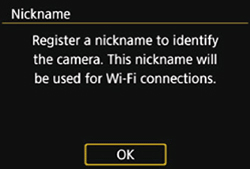
NOTE
When this setting is selected for the first time, a screen to register a nickname (name) is displayed.
When the camera is connected to another device wirelessly, the nickname will be displayed on the device. Be sure to set this.
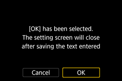
Select [OK] and enter a nickname (you can enter between 1 to 10 characters).
When you are finished, press the <MENU> button.
 ã 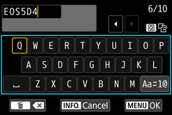 Select [OK] on the confirmation dialog and press < >. The nickname is registered and the [Wi-Fi function] screen is displayed.
*For details on how to use the keyboard, please refer to "Operation Reference: Virtual Keyboard Operation".
7. The [Wi-Fi function] screen is displayed.
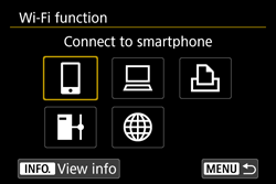
This completes the basic settings of the camera.
Step 3. Connect the Camera And the Computer
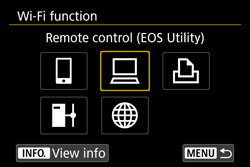
1. Select [  ] and press < >.
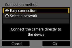
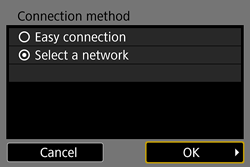
2. Select [Select a network], press <OK>, then press < >.

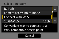
3. Select the wireless LAN setup method. Use the following method to connect to an access point.
When your access point supports WPS:
3A. Connecting via WPS (PBC mode)
3B. Connecting via WPS (PIN mode)
When your access point does not support WPS:
3C. Detecting and connecting to a network manually
IMPORTANT
If stealth functions of the access point are active, connection may be disabled. Deactivate stealth functions.
NOTE
- WPS (Wi-Fi Protected Setup) is a structure for simplifying settings when connecting one Wi-Fi device to another.
-In pushbutton connection mode (PBC mode), the camera and the access point can be connected simply by pressing the WPS button on the access point.
-In PIN code connection mode (PIN mode), an 8-digit identification number specified on the camera is set at the access point to establish a connection.
- Refer to the access point instruction manual to check if the access point you use is WPS-compatible.
3A. Connecting via WPS (PBC mode)
NOTE
- Check the position of the WPS button on the access point in advance.
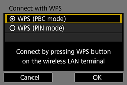
3A-1. Turn the < > dial to select [Connect with WPS] and press < >.
3A-2. Turn the < > dial to select [WPS (PBC mode)], then press < >.
- Select [OK] and press < > to go to the next screen.
3A-3. Press and hold the access point's WPS button for a few seconds.
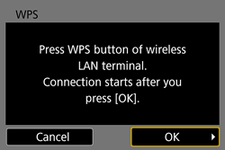
NOTE
A WPS connection button is affixed to your access point (wireless router, etc.). For further details on the location and how many seconds to press it, refer to the access point instruction manual.
3A-4. Select [OK] and press < > to establish a connection with the access point.
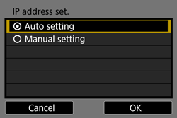
- When a connection with the access point is established, the [IP address set.] screen is displayed.
3A-5. Turn the < > dial to select [Auto setting], then press < >.
- Select [OK] and press < > to go to the next screen.
After you finish these settings, proceed to step 5.
3B. Connecting via WPS (PIN mode)
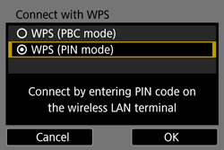
3B-1. Turn the < > dial to select [Connect with WPS].
3B-2. Turn the < > dial to select [WPS (PIN mode)], then press < >.
- Select [OK] and press < > to go to the next screen.
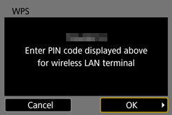
3B-3. At the access point, set the 8-digit PIN code displayed on the camera's LCD monitor.
- Select [OK] and press < > to go to the next screen.
NOTE
For instructions on setting PIN codes at the access point, refer to the access point's instruction manual.
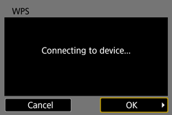
3B-4. Select [OK] and press < > to establish a connection with the access point.
- When a connection with the access point is established, the [IP address set.] screen is displayed.
NOTE
- It may take approx. one minute to establish a connection.
3B-5. Turn the < > dial to select [Auto setting], then press < >.
- Select [OK] and press < > to go to the next screen.
After you finish these settings, proceed to step 5.
3C. Detecting and connecting to a network manually
REFERENCE
This camera supports the following options for [Authentication] and [Encryption settings]. Therefore, set the encryption used by the access point to one of the following.
[Authentication]: Open system, Shared key, WPA-PSK, WPA2-PSK
[Encryption settings]: WEP, TKIP, AES
3C-1. The access point's SSID, encryption key, and key index (when WEP encryption is used) are necessary for connection. Refer to the access point's instruction manual to check the access point's SSID, encryption key, and key index.
NOTE
- SSID is a predetermined string of numbers and letters used to identify a specific access point. This is also called an "access point name" or "network name".
- The security method is a method for encrypting the data transferred via Wi-Fi.
- The encryption key (network key) is a key for encrypting the data transferred via Wi-Fi.
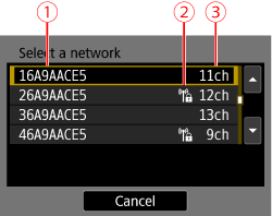
3C-2. Turn the < > dial to select the access point to connect to, and then press < >.  SSID  An icon is displayed if the access point is encrypted  Channel used
NOTE
- Scroll down the screen in step 5 to display [Refresh] and [Manual settings].
- To search for access points again, select [Refresh].
- To configure settings for the access point manually, select [Manual settings]. Enter the SSID using the virtual keyboard and then configure settings following the instructions displayed.
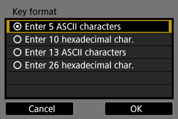
3C-3. Turn the < > dial to select the format and the number of characters used for the key, and then press < >.
- Select [OK] and press < > to go to the next screen.
NOTE
The screens displayed in steps 3C-3 to 3C-4 vary depending on the authentication and encryption specified for the access point.
REFERENCE
The [Key index] screen is displayed only if WEP encryption is used by the access point.
Select the key index number specified for the access point, then press < >.
- Select [OK] and press < > to go to the screen for step 3C-3.
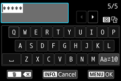
3C-4. Enter the encryption key using the virtual keyboard, then press the <MENU> button.
- When a connection with the access point is established, the [IP address set.] screen is displayed.
3C-5. Turn the < > dial to select [Auto setting], then press < >.
- Select [OK] and press < > to go to the next screen.
REFERENCE
[Auto setting]
- Settings otherwise configured with [Manual setting] can be configured automatically. However, the IP address and similar settings must be automatically assigned and configured in environments using DHCP servers or access points or routers supporting DHCP server functions. If an error is displayed, select [Manual setting] regardless of whether the IP address and similar settings are automatically assigned and configured.
[Manual setting]
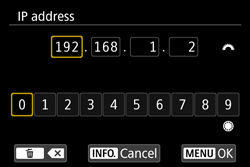
- If [Auto setting] results in an error, enter the IP address manually. For the IP address, enter the IP address assigned to the camera. Enter the [IP address], [Subnet mask], [Gateway], and [DNS address] on each screen as they are displayed.
- When entering numbers for the IP address, subnet mask, and so on, turn the < > dial to move the input position in the upper area and turn the <
 > dial to select the number. Press < > to enter the selected number. > dial to select the number. Press < > to enter the selected number.
- When you are finished, press the <MENU> button to configure the settings. A confirmation dialog is not displayed.
After you finish these settings, proceed to step 5.
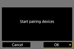
5. You can use the included "Pairing Software" to establish a connection between the camera and the computer.
- Turn the < > dial to select [OK], then press < >.
6. The following message is displayed. "******" represents the last six digits of the MAC address of the camera to be connected.
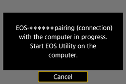
7. Start EOS Utility Ver.3.x.
For Windows 7, click the [Start] button and select [All Programs] ->[ Canon Utilities ] ->[ EOS Utility ] ->[ EOS Utility ].
NOTE
- For Windows 8, right-click the [Start] screen, then click [All Apps] on the bottom right side of the screen. On the [Apps] screen that is displayed, click [EOS Utility].
- For Windows 8.1, click [
 ] on the bottom left side of the [Start] screen. On the [Apps] screen that is displayed, click [EOS Utility]. ] on the bottom left side of the [Start] screen. On the [Apps] screen that is displayed, click [EOS Utility].
- For Windows 10, click the [Start] button, then click [All Apps] and then click [EOS Utility].
- For Mac OS X, click the [EOS Utility] icon in the Dock.
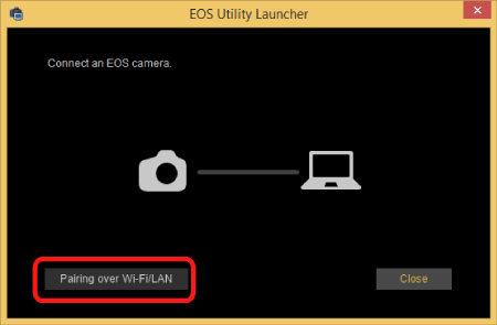
8. In EOS Utility, click [Pairing over Wi-Fi/LAN].
If a firewall-related message is displayed, select [Yes].
9. A list of detected cameras is displayed. Click [Connect].
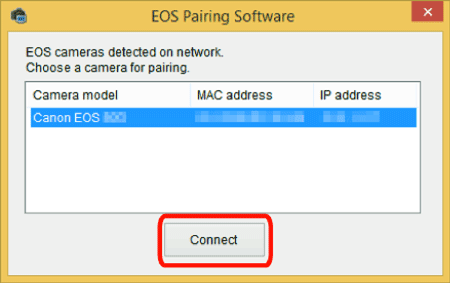
NOTE
- If a camera is already connected, it is not displayed in the list.
- If multiple cameras are displayed, identify the camera to connect to by its MAC address displayed on the camera's LCD monitor.
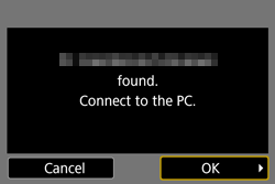
10. When the camera detects the computer on which you clicked [Connect] in step 9, the screen below is displayed.
- Turn the < > dial and select [OK], and then press < >.
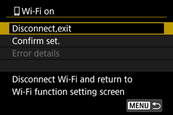
11. When a connection is established between the camera and the computer, the [ Wi-Fi on ] screen will appear on the camera.
NOTE
There is no need to complete pairing again if you will continue using a particular camera and computer together after pairing without changing the settings. When you use the camera next time, simply turn on the camera's power switch and start the Pairing Software. This will automatically connect the camera and the computer.
Connecting the camera and the computer is now complete.
Step 4. Send Images To the Computer
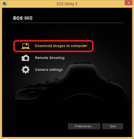
1. After the main window of EOS Utility appears, click [Download Images to Computer].
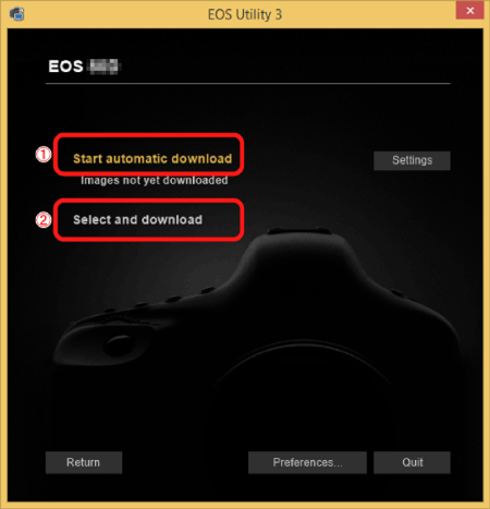
2. When the following window appears, click either - [Start automatic download] or - lets you [Select and download images].
NOTE
By default, downloaded images are saved in [Pictures]. You can change the save destination for images downloaded and images to download in [Preference].
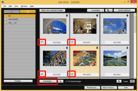
3. If you have selected [Select and download images] in step 2, the viewer window appears and the images in the memory card are displayed in a list.
In the displayed list of images, checkmark the images to download and click [Download] (here, 4 images are selected.)
If you have selected [Start automatic download], proceed to step 6.
NOTE
- You can click [
 ] to change the thumbnail order. ] to change the thumbnail order.
- For movie files, the [
 ] icon appears on the top left of the image. ] icon appears on the top left of the image.
- You can click [
 ] in the upper right of the window to sort the images with various conditions and choose images you want to download. ] in the upper right of the window to sort the images with various conditions and choose images you want to download.
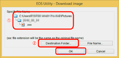
4. The [Download image] dialog box appears. To change the save destination, click [Destination Folder] and in the dialog box that appears, change the destination. Click [OK].
Displays the save destination on the computer Specify the save destination
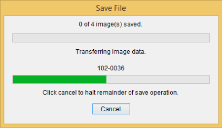
5. The images are downloaded to your computer.
6. When images have been downloaded, Digital Photo Professional starts up automatically and the downloaded images are displayed.
NOTE
- For details on using Digital Photo Professional to perform image editing and other operations, refer to the software instruction manual.
Downloading images is now complete.
Back to top
Virtual Keyboard Operation
For details on keyboard operation when registering cameraâs nickname (for identification), refer to the following.
You can change the nickname later on the [Geneal sett.] screen.
| Changing the entry area |
Press the button to toggle between the top and bottom entry areas. |
| Moving the cursor |
Use or  in the top area to move the cursor. in the top area to move the cursor. |
| Entering text |
In the bottom area, use or to select a character, then press to enter it.
You can check how many characters you have entered and how many more can be entered by referring to [*/*] on the upper right of the screen. |
| Changing the entry mode* |
Select  at the bottom right of the bottom entry area. Each time you press the entry mode will change as follows: Lower case â Numerals / Symbols 1 â Numerals / Symbols 2 â Upper case. at the bottom right of the bottom entry area. Each time you press the entry mode will change as follows: Lower case â Numerals / Symbols 1 â Numerals / Symbols 2 â Upper case.
*When [Touch control: Disable] is set, you can enter all characters on one screen. |
| Deleting a character |
Press the  button to delete one character. button to delete one character. |
| Finishing the text entry |
Press the MENU button to confirm what you have entered and exit. If a confirmation dialog is displayed, select [OK] to exit. |
| Canceling the text entry |
Press the INFO. button to cancel text entry and exit. If a confirmation dialog is displayed, select [OK] to exit. |
|