Names and Functions of Parts of the ScanFront 400
| Article ID: ART166841 |
| |
Date published: 11/23/2016 |
| |
Date last updated: 11/23/2016 |
Description
The names and functions of the parts of the ScanFront are shown below.
Solution
Front and Document Feed and Eject Trays
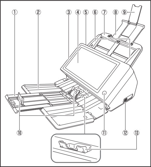
- Tray Extension
Open this to prevent scanned documents from slipping off.
- Document Eject Tray
Open this tray when using the ScanFront.
- Panel Unit
Open this when there is a paper jam or to perform maintenance.
- Touch Panel
Touch this screen to operate the ScanFront.
- Lock Lever
Locks the panel unit. Pull the lever towards you to unlock the panel unit.
- Document Guides
Adjust these to match the width of the document.
- Document Feed Tray
Place documents here.
- Feed Support
Pull this out to support loaded documents.
- Feed Extension Support
Open this when placing long paper in the scanner.
- Document Eject Stopper
This prevents the ejected documents from falling out of the document eject tray and aligns their leading edges. It can be moved to match the length of the document. The angle of the document eject stopper on the document eject tray will change depending on the volume of documents ejected.
- Power Button
Press this to turn on the scanner. When pressed, the power indicator is lit. Use the Power OFF button on the touch panel to turn the power OFF. The power button lights or flashes as follows depending on the scanner status.
| Power Button Indication |
Description |
| Lit |
Power is on |
| Flashing |
Low power mode |
- USB Port (Front)
Connect a USB 1.1/Hi-Speed USB 2.0 compatible USB memory device, USB keyboard, or USB mouse.
- Eject Tray Support
Open this when scanning multiple documents of varying sizes at one time. Scanned documents are arranged in the tray by supporting and lifting up the document eject tray from the bottom.
Rear
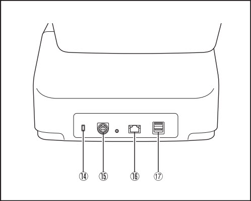
- Kensington Slot
This is an anti-theft slot that enables a key chain or lock to be connected to prevent theft.
- Power Connector (24 V DC)
Connect the plug of the supplied AC adapter.
- LAN Port (RJ-45)
Connect an RJ-45 (10Base-T/100Base-TX/1000Base-T) compatible network cable.
- USB Ports (Right Rear)
Connect a USB 1.1/Hi-Speed USB 2.0 compatible USB memory device, USB keyboard, or USB mouse.
