Waveform Monitor
The camcorder can display a simplified waveform monitor on the LCD screen, viewfinder and external monitors (SDI terminal or HDMI OUT terminal).
Operating modes:

Displaying the Waveform Monitor
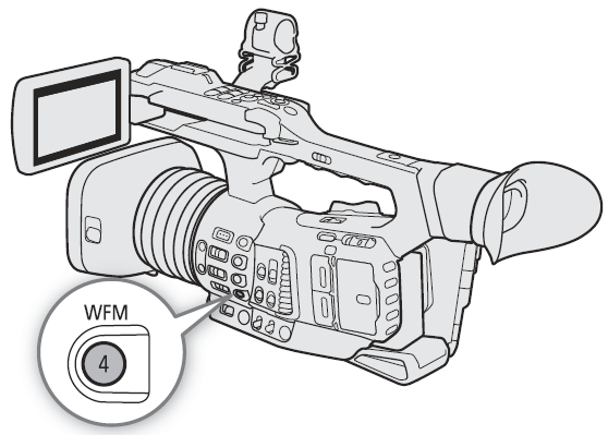
Press the WFM button to display the waveform monitor.
• The waveform monitor window will appear at the right of the screen.
• You can use the   settings to turn the waveform monitor display on and off separately on the LCD screen, viewfinder and external monitors connected to the respective terminals. settings to turn the waveform monitor display on and off separately on the LCD screen, viewfinder and external monitors connected to the respective terminals.
• You can use the   setting to display the waveform monitor on the left/right of the screen. setting to display the waveform monitor on the left/right of the screen. |
 |
Configuring the Waveform Monitor
1 Select the waveform monitor's [Type].

2 Select the desired option and then press SET.
- If you selected [Select Line], continue the procedure to set the Y coordinate of the line you wish to display. Otherwise, skip to step 6 to change the gain.
3 To select the line’s Y coordinate, select [Select Line].

4 Push the joystick up/down to select the first digit of the Y coordinate and then press SET to move to the next.
- Change the rest of the digits in the same way.
- When the number of horizontal lines (vertical component) of the resolution used is 1080, you can select a value between 0 and 1079 (1-line increments); when the vertical resolution is 2160, you can select a value between 0 and 2158 (2-line increments).
5 Select [Set] and then press SET.
6 Select [Gain].
7 Select the desired amplification ratio ([1x] or [2x]) and then press SET.
- If you selected [1x], the rest of the procedure is not necessary. If you selected [2x], the display range of the waveform monitor’s Y axis will be reduced by half. Continue the procedure to select the minimum luminance value (in %) shown on the Y axis.
8 Select [Y Position].

9 Select the desired percentage and then press SET.
Options for [Type]
[Line]: Sets the waveform monitor to line display mode.
[Line+Spot]: The waveform of the area in the red frame is displayed in red on top of the [Line] mode waveform.
[Select Line]: The selected horizontal line will be displayed along with its waveform.
[Field]: Sets the waveform monitor to field display mode.
[RGB]: Functions like an RGB parade scope.
[YPbPr]: Functions like a YPbPr parade scope.
NOTES
- The waveform monitor will not be affected even if a LUT is applied to the LCD screen, viewfinder or video output from the SDI terminal or HDMI OUT terminal.
- The waveform monitor cannot be displayed while the color bars are displayed or magnification is activated.
- If the [Knee] settings in the custom picture file (A126) were changed, a horizontal line will appear on the waveform monitor indicating the luminance (Y) level corresponding to the knee point.
